


UML Class Relationship Diagrams
Steven Zeil
Next we turn to more formal documentation that you can expect to show outside your team and probably to retain for the lifetime of the project.
We will employ UML notation for this.
-
UML notation has quickly become an industry standard
-
with applications outside of “traditional” software engineering: e.g., DBs
UML Diagrams
UML provides a number of different diagrams
- use case diagrams
- class relationship diagrams
- interaction diagrams
- sequence diagrams
- collaboration diagrams
-
package diagrams
- state diagrams
- activity diagrams
- deployment diagrams
We’ll look eventually at the ones shown in italics, starting with class relationship diagrams.
Diagramming in Context
The diagrams are part of an overall documentation strategy.
The purpose of that strategy is communication.
-
We don’t usually draw diagrams to stand by themselves.
-
Instead, like the diagrams that appear in, say, your textbook, each one is intended as part of a larger document, much of which will be explanatory text.
-
Furthermore, we draw diagrams for the same reasons we write sentences and paragraphs, to communicate some specific idea.
-
If a diagram is too complicated to be understood, it’s no more use than a sentence that is too complicated to be understood.
-
If a diagram is too vague to convey any definite meaning, it has no more value than an equally vague sentence.
-
-
-
The success or failure of a diagram lies entirely in its ability to communicate what the author intended.
-
The diagrams are actually the representation of a formal “language” and are expected to make statements that are meaningful according to the rules of that language.
1 Class Relationship Diagrams
A class relationship diagram describes the types of objects in the system and selected static relationships among them.
The relationships can be
-
generalization (e.g., a Librarian is a specialized kind of Library Staff)
-
association (e.g., a Patron may have up to 20 Publications checked out at one time)
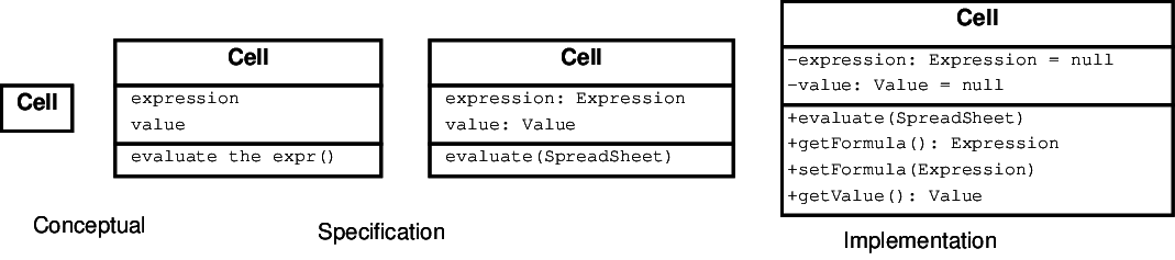
Perspectives
A diagram can be interpreted from various perspectives:
- Conceptual: represents the concepts in the domain
- perhaps only loosely related to the software classes that will implement them
-
Specification: focus is on the interfaces of ADTs in the software.
-
Implementation: describes how classes will implement their interfaces
The perspective affects the amount of detail to be supplied and the kinds of relationships worth presenting.
The choice of perspective depends on how far along you are in the development process. During the formulation of a domain model, for example, you would seldom move past the conceptual perspective. Analysis models will typically feature a mix of conceptual and specification perspectives. Design model development will typically start with heavy emphasis on the specification perspective, and evolve into the implementation perspective.
The choice of perspective also depends on the context of the document in which it appears. We don’t create diagrams just for the sake of creating diagrams. We create them to communicate with someone. Diagrams are a part of an overall documentation process. If you think about the diagrams that appear, for example, in one of your textbooks, you don’t see page after page of diagrams without supporting text. Instead, the diagrams are presented along with explanatory text, as a way of clarifying and emphasizing points being made in the overall narrative flow of the document. Good diagrams can reduce the amount of wordy and often technically stilted text that would otherwise be required.
The same is true when documenting a model. If you are trying to explain a concept in your model, an accompanying diagram should be at the conceptual level. If you are trying to explain the details of how objects interact, the specification perspective may be more appropriate. if you are trying to explain an unexpected feature of how you have implemented or plan to implement a feature, you are probably going to portray things from an implementation perspective. Even late in the development of the design model, you may find it necessary to switch back and forth from one perspective to another in order to be an effective communicator.
2 A Class, in Isolation
A class can be diagrammed as
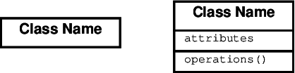
We’ve already seen the three-part form of this.
But in the course of writing a full set of documentation, a class might appear multiple times in different diagrams. It could be distracting to list out all of tha attributes and operations every time it appears.
Instead, you can use the simpler name-only form when discussing a class whose attribute and operation details are given elsewhere, particularly if the attributes and operations of the class were not relevant to the idea you wanted that diagram to communicate.
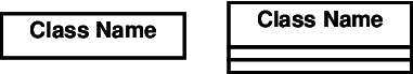
Even an Empty Section has Meaning
Note that these are not equivalent:
-
The left diagram says that we aren’t discussing the attributes and operations.
-
The right diagram says that this class has no attributes and operations.
-
Some authors might show some attributes and operations in one diagram and others in another, in order to focus attention on the ones relevant to the current discussion.
In that case, we would say that the right diagram means that there are no relevant attributes and operations.
-
2.1 Attributes
Attributes are given as
visibility name: type = defaultValue
Only the name or type is required. The others may be added when relevant:
- visibility: + (public), # (protected), or - (private)
-
Only for implementation perspective.
When you are only talking about concepts or interface specifications, the idea of a “private” anything is irrelevant.
-
Attributes are usually single values.
- Ones that take multiple values (lists, etc.) are generally represented using associations.
2.2 Operations
Operations are given as
visibility name (parameterlist) : return-type
Again, the amount of detail depends on the perspective (and on how much has actually been decided)
3 Generalization Relationships
A class (the “subtype”) is considered to be a specialized form of another class (the “supertype”) or, alternatively, the supertype is a generalization of the subtype if
-
conceptual: all instances of the subtype are also instances of the supertype
-
specification: the interface of the subtype contains all elements of the interface of the supertype
-
The subtype’s interface is said to conform to the interface of the supertype
-
implementation: the subtype inherits all attributes and operations of the supertype
Diagramming Generalization
The UML symbol for this relationship is an arrow with an unfilled, triangular head.
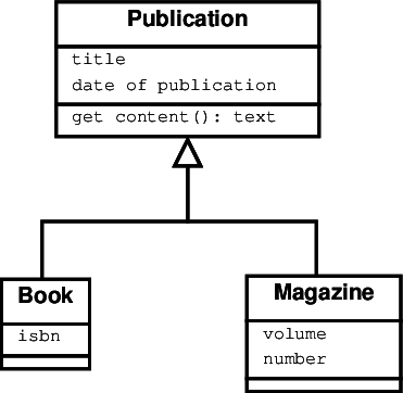 Read this arrow as “is a specialization of”, “is a kind of”, or “is a”. (The latter can be a bit ambiguous however, as we might also say that Webster’s Dictionary “is a” Book, but that’s not a generalization relationship.
We infer from the relationship that books and magazines have titles and dates of publication and that we can get their content. However, not all publications have ISBNs.
Multiple Specializations
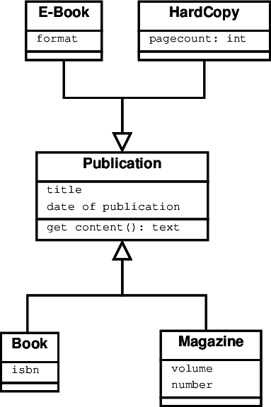 Some classes may participate in multiple generalization relationships. The arrows are grouped together to indicate related, mutually exclusive, divisions:
4 Associations
-
An association is any kind of relationship between instances of classes.
- Generalization is not an association because it is a relation between the classes themselves, not between their instances (objects).
-
In a conceptual perspective, associations represent general relationships. In a specification perspective, associations often denote responsibilities.
Diagramming Associations
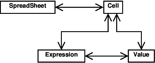
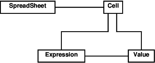 Associations are shown as lines connecting classes.
-
Plain associations like these are not particularly useful.
-
This one tells us, for example, that some spreadsheets have some kind of relationship with some cells.
- Only in very rare circumstances would that be a useful insight into the author’s understanding of the spreadsheet world.
Decorations
 We make the associations meaningful by attaching various decorations.
4.1 Naming Your Relationships
Relationship Names
Most important of these are the decorations that name the relationship being shown.
-
Names: Names of relationships are written in the middle of the association line.
-
Good relation names make sense when you read them out loud:
- “Every spreadsheet contains some number of cells”,
- “an expression evaluates to a value”
-
They often have a small arrowhead to show the direction in which direction to read the relationship, e.g., expressions evaluate to values, but values do not evaluate to expressions.
Roles
-
Roles: a role is a directional purpose of an association.
-
Roles are written at the ends of an association line and describe the purpose played by the associated class in the relationship.
-
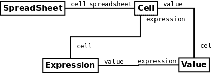
E.g., A cell is related to an expression. The nature of the relationship is that the expression is the formula of the cell.
-
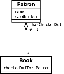
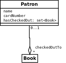
Roles and Attributes
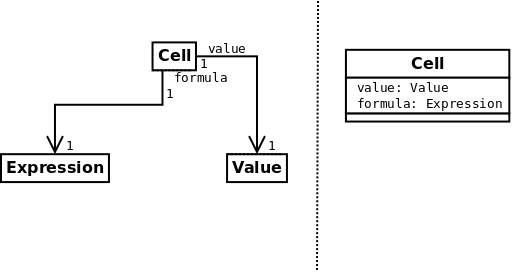
In a specification or implementation perspective, roles often correspond to attribute names. These two representations are, in a sense, equivalent.
- If we have conventions for naming attribute retrieval functions (e.g., get/set) , we can infer those from the role name.
Roles versus Attributes
When should you use attributes within a class and when should you use associations with role names?
-
Lean towards using associations when the relationship is not one-to-one.
-
Use associations when you want to target the attribute’s class for other associations (e.g., the “evaluates to” association in the earlier diagram.
Unnamed Associations are Useless
As a rule, I would argue that every association should have either a name or roles
- However, generic names like “has”, “contains”, or “is a” should be avoided by using one of the specialized associations described later.
Unnamed Associations are Useless (cont.)
Not everyone agrees.
- Some authors suggest that, if neither is given explicitly, then the association should be considered to have roles named for the classes.
-
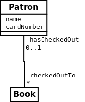
In other words, this
-
would default to
Neither of these is an attractive choice, but, in practice, there are generally better options.
4.2 Multiplicity
Multiplicity indicates how many instances of a class participate in the relationship.
Multiplicity is encoded as:
-
k: Exactly k instances (where k is an integer or a known constant) -
k..m: Some value in the range from k to m (inclusive) -
*: Denotes the range 0..infinity. Can also be used on the upper end of a “..”, e.g., 1..* means “at least one”.
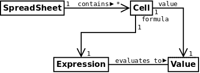
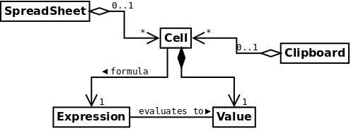
Diagramming Multiplicity
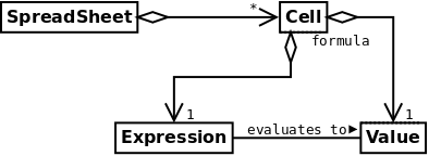
This diagram above indicates that
-
each spreadsheet contains any number of cells, but that
-
a cell is contained within exactly one spreadsheet.
-
Each cell contains exactly one expression and one value, and these values and expressions are not shared with other cells.
4.3 Navigability
Navigability arrows indicate whether, given one instance participating in a relationship, it is possible to determine the instances of the other class that are related to it.
The diagram above suggests that,
-
given a spreadsheet, we can locate all of the cells that it contains, but that
- we cannot determine from a cell in what spreadsheet it is contained.
-
Given a cell, we can obtain the related expression and value, but
- given a value (or expression) we cannot find the cell of which those are attributes.
Navigability and Role Names
There’s a relationship between navigability and role names.
In perspectives and relationships where the role names are attribute names, we would not have a role name for an un-navigable direction of an association.
Hence, we have no role name naming the cell related to a value or expression.
Navigability and Perspectives
-
Navigability is probably not useful in most conceptual diagrams.
-
In a specification/implementation diagram, if no arrows are shown on an association, navigability defaults to two-way.
For example, in a specification perspective, this
defaults to
- In an implementation perspective, this would imply pointers in each object going to the related objects.
5 Specialized Associations
Certain kinds of associations occur so frequently that they are given special symbols that replace names and (often) role labels.
5.1 Aggregation
Denoted by an arrowhead drawn as an unfilled diamond, aggregation can be read as “is part of” or, in the opposite direction as “has a”.
 This diagram suggests that cells are part of a spreadsheet and that an expression and a value are each part of a cell.
Aggregation Details
-
The multiplicity at the arrowhead defaults to “1”.
-
Aggregation is almost never named and roles are only used if the attribute name would be unexpected.
-
There is a lot of variation in deciding when to use use aggregation.
- For example, experts might disagree on whether a Library can be represented as an aggregate of its Librarians and of its Patrons.
- I recommend reading your suggested aggregations, out loud, as “is part of” and asking yourself whether they make sense.
Example: Should This Be Aggregation?
 For example, this diagram tries to circumvent our rule that attributes are single-valued by having a “single” set as an attribute.
-
That would be OK in an implementation perspective (i.e., in a design model),
-
but not in an earlier model/perspective where it prematurely suggests a data structure.
- Though if a more neutral “seq. of” or “coll. of” were used, it might be OK.
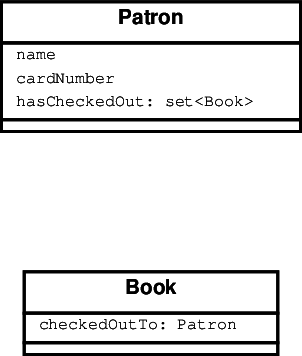
Example: Should This Be Aggregation? (2)
-
This alternative would also be OK in a design model.
-
But it’s terrible in a conceptual perspective and uncomfortable in a specification perspective.
-
If I read this as “books can be part of a patron”, I get a mental picture of books being surgically implanted into people. I would not accept that in a domain or analysis model.
-
Example: Should This Be Aggregation? (3)
 This one is no better in the earlier perspectives.
- If “a patron can be part of a book”, does that mean that I will find flat little people pressed between the pages?
-
I’m starting to feel like I will never visit a library again.
-
Example: Should This Be Aggregation? (4)
 So, for conceptual or specification perspectives, I’d avoid aggregation in this case and fall back to a general association.
- (This also captures the bi-directional navigability with a bit more elegance as well.)
5.2 Composition
Composition is stronger form of aggregation. It implies that the “lifetime” of the parts is bound to the lifetime of the whole.
-
The usual test to see if composition applies is to ask, “if I delete/destroy the container, do the parts go away as well?”
-
Composition is denoted by an arrowhead drawn as a filled-in diamond.
Composition Example
 This diagram suggests that destroying a cell would also destroy its value and formula. That makes sense if the cell does not share those components with other objects.
However, destroying a spreadsheet does not necessarily destroy its cells.
- (We can infer that because, if the cells have been cut or copied to the clipboard, the spreadsheet could be destroyed and yet the cells would remain available for pasting into some other spreadsheet.)
5.3 Qualification
A qualified association describes a situation in which one class is related to multiple instances of another, but the collection of related instances is “indexed” by a third class.
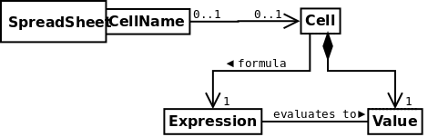
- This diagram indicates that a spreadsheet provides access to cells retrieved by cell name. It suggests an eventual implementation by something along the lines of a map or table.
5.4 Dependency
A class A depends on another class B if a change to the interface of B might require alteration of A.
-
A dependency is indicated by a dashed line ending at a navigability arrow head.
-
Dependencies have little use outside of an implementation perspective.
Dependency Example
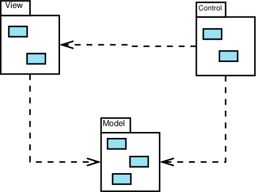 This diagram shows a system that has been decomposed into three major subsystems.
-
The Model is the core data – the stuff that this program is really all about.
-
The View is the portion of the code responsible for printing or drawing portrayals of the model data - for example, code to render graphics on a screen as part of a GUI.
-
The Controller is the portion of the code responsible for accepting interactive inputs (mouse clicks, key presses, etc) and responding to them.
MVC
The dependencies shown here are the defining characteristic of the MVC approach to user interface design:
- the controller depends upon, and therefore can make calls upon, the model
- (e.g., if someone enters a new data value via a GUI) and upon the view (e.g., someone clicks on a scroll bar or zoom button to alter the view without actually affecting the data).
MVC
The dependencies shown here are the defining characteristic of the MVC approach to user interface design:
-
the controller depends upon, and therefore can make calls upon, the model
-
Neither the view nor the model depend on the controller.
-
The view depends on the model
- you can’t draw something without being able to look at it.
-
But the model does not depend on the view.
Why MVC?
The advantage of this interface design is that we can radically change the user interface without altering the core computations (the model).
6 Other Class Diagram Elements
We won’t use these as often, but you should be able to recognize them.
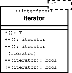
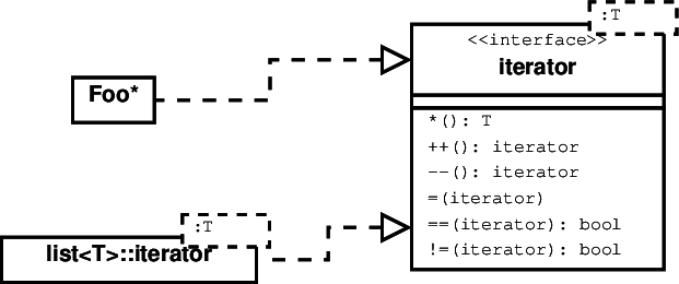
Parameterized Classes
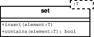 Used to represent templates and similar concepts.
Constraints
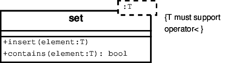 Constraints can be added almost any place by writing them within brackets.
Stereotypes
Stereotypes are an extension mechanism built in to UML. Written within <<…>>, these are labels used to indicate that you are deviating slightly from the standard interpretation of a UML construct.
 For example, an interface is a collection of related operations.
- It is not a full-fledged class.
- We represent it, however, as a variation on the normal idea of a class.
Satisfies / Realizes
Another specialized association, this is actually a combination of dependency with the arrowhead of generalization.
7 Drawing UML Class Diagrams
In theory, you can use almost any drawing tool.
-
But general-purpose tools offer you more opportunities to mess up
-
Better to use a tool that “understands” UML
On our systems, we have
-
dia, an open-source product (Windows & Linux)
- recommended
-
Visio, a commercial product from Microsoft (Windows)
- Impossible to do some standard UML things
-
omit visibility markers
-
- Frustrating to do others:
- getting a simple 1-box class,
- using user-defined types for attributes & function parameters
- Impossible to do some standard UML things
Data Entry Rather than Direct Formatting
- Both tools work by allowing you to create a class box, then editing its properties
- These properties include attributes and operations
Exporting the Final Product
-
As a general rule, you edit and save your documents in the tool’s native file format
-
Then export as graphics to be pasted into your documentation
-
Use vector graphics formats whenever possible
- e.g., Use: PDF, EPS, SVG, WMF, EMF
-
Best choice depends on what your document tool can import
- Avoid: GIF, BMP, , PNG
- Especially avoid “lossy” raster formats: JPEG
-
8 The Documentation Narrative
Remember, we don’t draw diagrams just for the sake of drawing diagrams. Diagrams should contribute to an overall narrative describing our model. (An example will be shown in the next set of notes.)
As we construct this narrative, we should merge the attribute and operation information from our isolated class diagrams into the diagrams so that no information is lost.
-
Every class should be shown with its full set of known attributes and operations at least once.
-
Generally, we would show the full class details once only, unless the attributes and operations are particularly relevant to understanding the narrative for multiple diagrams.
-
-
Technically, an isolated class diagram is a class relationship diagram. But such an un-informative choice is, at best, a missed opportunity.
Try to find a meaningful way to relate it to other classes in the model. -
Each diagram should tell a reasonably cohesive story and should contribute to the surrounding text.
-
Beware of massive diagrams that try to pack too much into a single picture. That’s every bit as bad as trying to cram all the ideas of a paper into a single paragraph.
-