


Sequence Diagrams
Steven Zeil
Sequence diagrams describe how groups of objects collaborate in some behavior.
- Important: these diagrams are about objects. The UML class diagrams that we looked at earlier are about (surprise!) classes.
1 UML: Objects vs. Classes
Remember that, in UML, these represent classes:
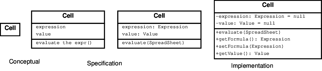
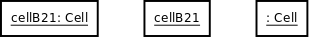
But now we want objects:
-
Note the underlining and non-bold face.
-
The syntax for the text describing the object is similar to the attributes in the class diagrams.
2 Sequence Diagrams
These diagrams attempt to show, for some specific use-case or some common interaction:
-
what objects are involved
-
what operations are involved, and on which objects
-
what the sequence of operations is
2.1 Sequence Diagram Components
Our domain or analysis models view the world as objects that interact by exchanging messages.
- Sequence diagrams allow us to demonstrate that our model suffices to represent a use case by mapping the steps of the use-case into specific messages (function calls) from one object to another.
-
Although sequence diagrams can be used to illustrate any interesting collaborations (sequences of related messages) among our objects, we most often draw one sequence diagram for each use case.
-
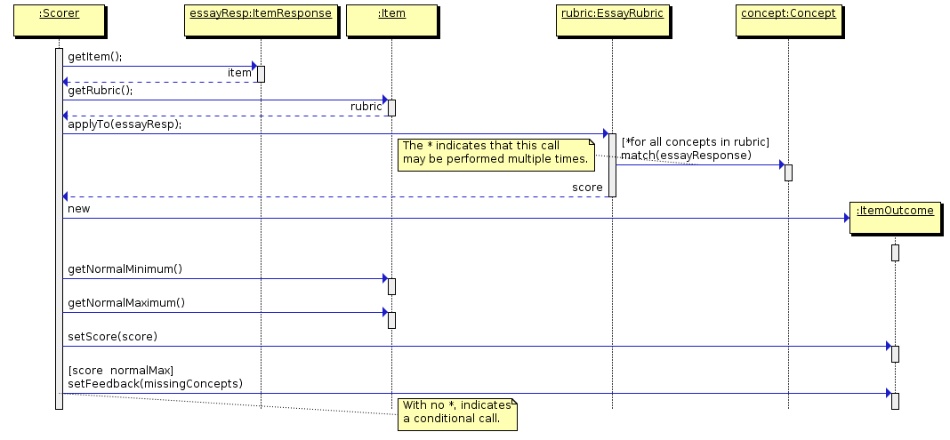
The Score Essay Use Case
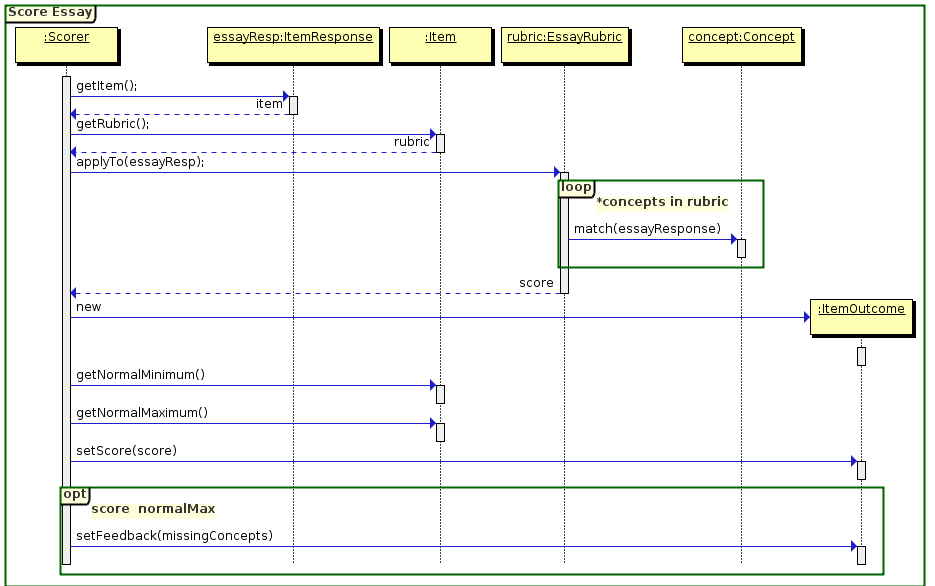
Here is a sequence diagram for our “Score Essay” use-case. To help understand this, we’ll take this apart, one element at a time, looking at what each one shows us.
2.1.1 Objects
-
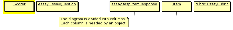
A sequence diagram is composed of a number of columns, each headed by an object.
- Human objects are often indicated by a stick figure. In general, objects are shown as rectangles.
-
Note that, unlike in the class relationship diagrams, the rectangles here denote individual objects, not classes.
If it seems confusing to use rectangles for both, there is a consistent way to tell them apart. In UML, the general form for an object declaration is
objectName : className
For example, chkTrans:Transaction indicates that we have an object named “chkTrans” of type “Transaction”.
Quite often, we know we want to discuss an object, but don’t really care to give it a name. For example, in all of our use-cases so far, there has been only a single checkbook. We know that it will be a member of the Checkbook class, but if we actually give it a name, the reader will think that’s something they are supposed to remember. Then, if we never actually use that name, we’ve distracted the reader for no good reason.
So UML allows us to drop the object name:
objectName : className
as we have done for several of the objects in the diagram above, including the checkbook.
The colon (:) in front to the remaining name is our cue that
-
This is still a representation of an object, not of a class, and
-
The name that follows is a class name.
In essence, we have an anonymous object of a known class.
2.1.2 Time Lines
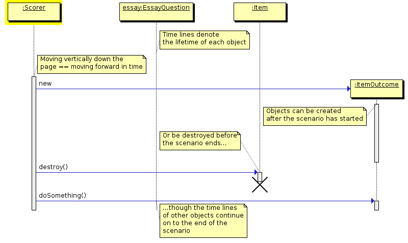
The dashed lines are called time lines.
-
As we move from the top of the diagram towards the bottom, we are moving forward in time.
-
Something that is drawn below a particular event actually occurs after it in our scenario.
-
If an object is created/destroyed as part of a scenario, it will be shown as a shorter time line.
We’ll see examples of this later.
2.1.3 Messages
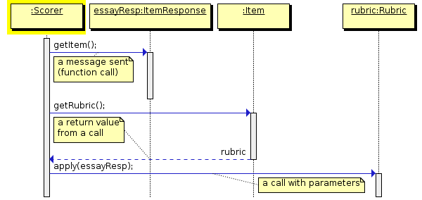
- Each solid arrow denotes the passing of a message from one object to another.
Or alternatively, a function call made by some code associated with the first object, calling a member function of the second object.
Parameters and Return Values
As with any function calls, these can include parameters.
- Functions can also have return values, shown as an arrow with a dashed line.
-
Normally, show these only when they are important to the understanding of a diagram (e.g., they match one of the named objects)
-
Sanity Check 1
Important Sanity Check: If you draw an arrow from one object of type
Cto an object of typeT, and you label that arrowfoo, then the classTmust have a function namedfoolisted as one of its member functions.
- If your domain/analysis model is still valid,
-
Discovering that your model is missing some operations is one of the advantages of doing sequence diagrams.
-
2.1.4 Activation Boxes
An activation of a function is the information associated with a particular call to that function, including all parameters, local variables, etc.
-
This is not specifically a UML term – it’s a common term when discussing function calls in any programming language, and how function calls are implemented in computer architectures.
-
If a function is recursive (calls itself or calls other functions that eventually call it), it can have multiple activations in memory at any given time.
Example of Activation Boxes
Sequence diagrams are all about time, so we sometimes need to indicate just how long a function call is active
-
i.e., how long we are executing its body or executing other function bodies called from it.
-
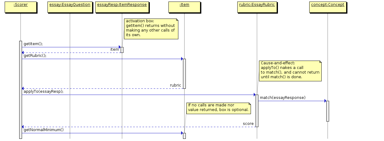
An activation box marks off the time from the start of execution of a function body to when we return from that body to its caller.
When to Show Activation Boxes
- You must show activation boxes if a the body of a called function makes other calls of its own, or if a function has a return arrow.
-
Activation boxes are essential to demonstrating cause-and-effect within the model
-
Now, a sequence diagram indicates the flow of time, but it’s not a strict graph. We can’t say that one inch of vertical space equals some number of seconds. All that we can say is that if A is drawn below B, than A occurs after B.
Look, then at the applyTo call from the scorer to the rubric. You can see an activation box starting there, indicating the start of the function body of EssayRubric::applyTo. A little time after that, you see an arrow emerging from that box. That arrow indicates that this function body of applyTo eventually calls concept.match(essayresponse). There you see another function body (of match) start to execute.
The particular drawing tool that I use insists on putting short activation boxes at the end of every call. If there are no further outgoing calls (e.g., getNormalMinimum()), these boxes are optional. A message arrow with no activation box on the end simply indicates that the function call issues no interesting messages of its own.
A function body that does issue a message must show an activation box so that we can see whence that message comes.
More Sanity Checks
Sanity check 2: An incoming arrow to an activation box must connect to the very top of that box.
- We do not have psychic functions that suddenly start executing themselves in anticipation of being called at some time in the future.
Sanity check 3: Every activation box must either
have exactly one incoming arrow, or
have no incoming arrows but belong to an autonomous object (e.g., a human) that initiates a task spontaneously (e.g., the scorer in this scenario).
More Sanity Checks
Sanity check 4: If a function body of
foocalls a functionbar, the activation box ofbarmust end above the end of the activation box offoo.
That’s just the way functions work.
- If
foocallsbar, thenfoocan’t actually do anything (including returning to its own caller) until afterbarreturns.
Sanity check 5: If an activation box has an outgoing “return value” arrow, that arrow must emerge from the very bottom of the box.
- Function bodies do not hang around chatting after they return control to their caller.
More Sanity Checks
Sanity check 6: If an activation box has an outgoing “return value” arrow, that arrow must point back to the caller of that function activation.
- That’s just the way functions work!
Activations Can Overlap (nest) in Time
The call/activation box symbols can easily accommodate simultaneous activations of different functions on the same object.
Example
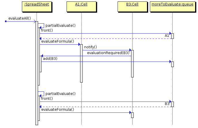
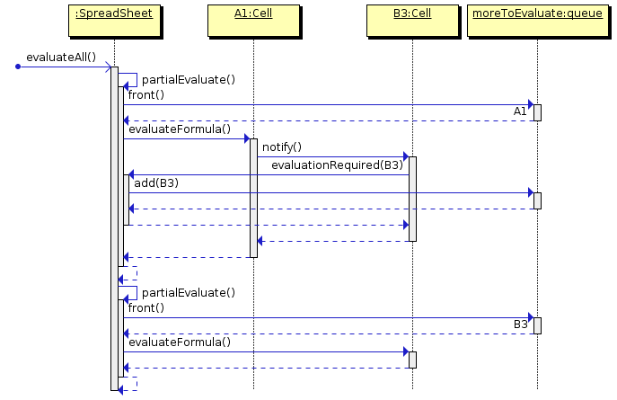
Suppose we have a spreadsheet in which cell B3 contains the fomula “A1+1” and that a new formula has recently been placed in A1. A spreadsheet is in the midst of a call to
// Re-evaluate all cells in the spreadsheet
int evaluateAll()   {
  while(moreToEvaluate())
     partialEvaluate();
  return evaluationCounter;
}
Each call to partialEvaluate causes one cell (e.g., A1) to be removed from a queue moreToEvaluate and then told to evaluate its formula.
- If that evaluation changes the value in A1, it notifies any cells that are observing it (e.g., B3).
- Those cells tell the spreadsheet that they require evaluation, and the spreadsheet adds them to the queue.
On a subsequent pass around the loop, the spreadsheet makes another call to partialEvaluate that results in B3 being pulled from the queue and evaluated.
Example: Seq Diagram
Observations:
-
The call to partialEvaluate() is a call from one member function of an object to another member function of the same object.
-
We often choose not to show these because they really have little to do with the idea of whether the public interface fo a class is OK.
-
Instead, usually concentrate on inter-object messages.
-
-
We have “unrolled” the loop in this diagram because I wanted to show the specific cells being manipulated each time around the loop.
-
We’ll see other approaches to handling loops shortly.
-
-
Note the stacking of the activation boxes on the SpreadSheet timeline to illustrate nested periods of time.
Returns
If you have trouble following the sequence of calls and returns, you can add in the return arrows from the bottom of each activation box:
Personally, I find the extra arrows distracting and don’t recommend them for general use. Save them for circumstances where the data being returned in important to the understanding of the diagram (e.g., where you give a name to the returned value so that you can use that name later in the diagram).
2.2 Control Flow
2.2.1 Guards
Guards are conditions attached to messages to indicate conditional execution or loops.
-
Guards are OK if only one call is repeated/conditional
-
They become confusing when a sequence of messages are affected.
2.2.2 Frames
UML 2.0 introduced frames to group messages
Most common varieties (identified by label):
-
diagram label
-
loop: repeated messages
-
opt: conditional messages
-
alt: if-then-else like construct
-
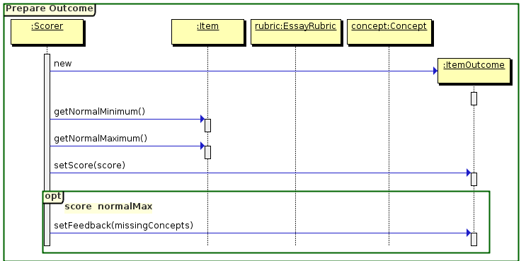
ref: reference to another diagram, becomes a “black box” in this diagram
Options and Loops
-
Grouping is indicated very naturally by the area of the enclosing rectangle. We can nest frames if we need to.
-
We use guard expressions (in the
[ ]) to indicate loop and option conditions.
Reference Frames
We use an outer frame to name our diagram
Referring to Other Frames
And then can reference it in other diagrams
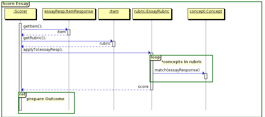
- These allow you to break up sequence diagrams into pieces and have some diagrams “include” or refer to other diagrams.