

 |
|
|
Abstract
Requirements documents are written in many different forms. We will look the components common to many of these, with particular attention to the distinction between functional requirements and nonfunctional requirements.
We will look, in detail, at a standard format for Software Requirements Specification (SRS) documents from the IEEE, and we will look more briefly at some alternatives.
Problems of requirements analysis
Waterfall processes often distinguished between
Requirements definitions: Customer-oriented descriptions of the system’s functions and constraints on its operation
Requirements specifications: Precise and detailed descriptions of the system’s functionality and constraints.
Functional requirements are statements of the services that the system should provide
Non-functional requirements are constraints on the services and functions offered by the system
Can lead to problems with
Some years ago, I worked on a series of research projects that made use of a Requirements Definition written by a NASA contractor, Charles Rivers Analytics. An updated copy of that document can be found here.
It describes a Redundant Strapped-Down Inertial Measurement Unit, a device that forms part of an aircraft’s navigation system. It uses a bank of accelerometers (sensors that can measure acceleration along a straight line) to determine, at any moment in time, how much and in what direction the aircraft is accelerating.
Integrated over time, the acceleration can yield the history of velocity changes by the aircraft. Integrated again, one can estimate how far and in what direction the aircraft has traveled.
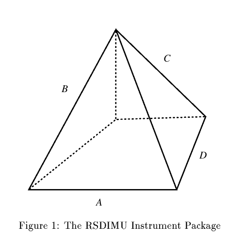
Physically, the RSDIMU consists of a square-based pyramid with the triangular faces being equilateral triangles (a semi-octahedron).
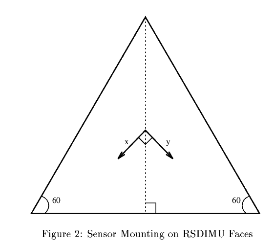
On each triangular face are mounted two sensors, at right angles to each other.
That gives a total of 8 sensors, all at varying angles to one another. That’s more than enough to determine the acceleration of the aircraft in 3 dimensions.
This redundancy (the “R” in RSDIMU) is important because:
Over time, some sensors may fail,
Like all physical measurement devices, the sensors are noisy – there are random errors in any real measurement process.
From the RSDIMU Requirements Definition:
An RSDIMU consists of a skewed array of redundant inertial sensors and exemplifies the current trend for designing hardware fault tolerant inertial measurement units (IMU’s) for high reliability applications. The portion of the RSDIMU you will handle contains eight linear accelerometers mounted on the four triangular faces of a semioctahedron.
Your procedure will have two functions, both of which are a consequence of the redundancy in the sensor complement of the RSDIMU. The first function is to perform a consistency check to detect and isolate failed sensors. The second is to use the sensors found to be good by the first check to provide estimates of the vehicle’s linear acceleration expressed as components along the north, east, and down axes of a navigational frame of reference.
⋮an RSDIMU as described here would operate as follows. With the vehicle stationary, as series of sensor readings would be taken over time, and this would comprise the calibration data set for that particular flight. During flight, the sensors would be read periodically at regular time intervals to provide input for the navigation software.
Critique
The preceding requirements mix up functional and non-functional requirements and are incomplete.
A simpler requirements definition.
Read through this.
The SRS (Software Requirements Specifications) adds detail to the requirements definition.
An SRS should be
Most of these are self-explanatory.
Requirements should be written so that they can be objectively verified
This is not good:
The system should be easy to use by experienced controllers and should be organized in such a way that user errors are minimized.
The error rate should be been quantified
Experienced controllers should be able to use all the system functions after a total of two hours training. After this training, the average number of errors made by experienced users should not exceed two per day.
Making the Subjective Objective
Some possible objective measures of properties that we often consider to be subjective:
| Property | Measure |
|---|---|
| (subjective) | (objective) |
| Speed | processed transactions / sec. |
| Response time | |
| screen refresh time | |
| Size | k bytes |
| Ease of use | training time |
| number of help frames | |
| Reliability | mean time to failure |
| probability of unavailability | |
| failure rate | |
| Robustness | time to restart after failure |
| probability of data corruption after failure | |
| Portability | % of target dependent statements |
| number of target systems |
Requirements traceability means that related requirements are linked in some way and that requirements are (perhaps) linked to their source
Improving Traceability
"23: The system shall do A and B.
into
"23: The system shall do A.
"24: The system shall do B.
so that we can talk about requirements being satisfied or failed on an individual basis.
Cross-reference related requirements using this unique number
Produce a cross-reference matrix for each requirements document showing related requirements.
There are many different styles for writing requirements.
The choice often depends on
Local culture – what the developers are familiar with.
Overall organization
Perhaps most common is the use of a mixture of natural language, mathematics, and diagrams, in a detailed numbered list:
3. Physical structure:
The RSDIMU is composed of an instrument and a display. The display is discussed in Section 6.3. This section is devoted to the structure of the instrument package.
3.1 The instrument package is a semi-octahedron (a square-based pyramid) (Figure 1).
3.1.1 It has four non-base faces, named
A,B,C, orD.3.1.2 Each face contains two sensors, named the
xandysensors.3.1.2.1 Associated with each sensor is a set of misalignment angles. These are specified further in Section 2.3.2.
Rationale: There is an ideal position for each sensor, but the physical mounting may differ slightly.
3.1.2.2 The misalignment angles are assumed to be small enough (less than 5 degrees) for the sine of the angle to be approximately equal to the value of the angle expressed in radians.
3.1.3 The temperature of the face,
temp, determines the temperatures of the sensors mounted on the face.Rationale: Sensor output varies with temperature (see section 4.6).
Each numbered item is a separate functional requirement.
These are often described as “The system shall…” statements.
As you can see, however, they often (and maybe preferably) refer to previously introduced subsystems.
Works well when organizing by feature.
A pre-condition is what must be true before a function can be performed.
A post-condition describes what the function will accomplish as a boolean expression that will be true upon completion.
Both pre-conditions and post-conditions must be boolean statements.
There is a long tradition of documenting both functions (design and implementation) and functionality (requirements) with pre-conditions and post-conditions:
Example 1: Example: RSDIMURSDIMU/Calibration/4.1
Function: Check for Noise
Description: The variance in a number of readings taken from one sensor while the vehicle was at rest are compared to a threshold value. Sensors whose variance exceeds the threshold are marked as failed due to excessive noise.
Inputs: Face, Sensor, raw sensor data collected on ground, noise threshold
Source: raw sensor data
offrawfrom external measurement procedureOutputs: Sensor failure
linFail& noise indicatorslinNoiseDestination: Edge consistency check and acceleration estimation functions
Requires: Instrument
Pre-condition: Sensor is not already marked as failed
Post-condition:
linFail[Face,Sensor]andlinNoise[Face,Sensor*]will be set to true ifstd-dev(offraw) > 3 * linstd.Side effects: Changes to sensor status affect face status as well.
The “Description” here is informal documentation.
The “real” specification is in the pre- and post- conditions and the side-effects.
The term side effect comes from programming where it refers to any effect of a function that cannot be observed by inspection of the return value and output parameters (e.g., changes to global variables).
Although this looks very low-level, the apparent variables and arrays like
linFailandlinNoiseare actually defined elsewhere as signals that appear as rows of green/red lights on an indicator panel.
Because pre- and post-conditions are booleans, they are often expressed in mathematical or even programming language notation.
Example 2: Pre- and Post-Conditions in API Documentationcatalog.h/* * catalog.h * * Created on: Apr 10, 2017 * Author: zeil */ #ifndef CATALOG_H_ #define CATALOG_H_ #include <string> #include <iostream> #include "book.h" /** * A list of books, identified by Gutenberg ID. */ class Catalog { public: /** * Create a new empty catalog, capable of holding up to * maxCapacity books. * * @param maxCapacity maximum number of books this catalog * can hold. */ Catalog (int maxCapacity = 100); /** * How many books currently in this catalog? * * @return number of books in the catalog. */ int size() const; /** * How many books can this catalog hold? * * @return max capacity of this catalog. */ int capacity() const; /** * Attempt to alter the capacity of this catalog so that * it can hold at least newCapcity books. Existing books * in the catalog are retained. * * @param newCapacity maximum number of books we would like to be able * to store in this catalog. * @post capacity() >= newCapacity */ void reserve (int newCapacity); /** * Add a book to the catalog. If a book with the same ID exists, it is * replaced by b. * * @pre size() < capacity() || contains(b.getID()) * @post contains(b.getID()) && b == get(b.getID()) */ void add (Book b); /** * Check to see if a book is contained in the catalog. * * @param bookID the ID string of a potential book * @returns true iff a book with that ID is in the catalog. */ bool contains(std::string bookID) const; /** * Return the book associated with a given ID. * * @param bookID the ID string of a potential book * @returns The book with that ID in the catalog, or * Book() if the ID is unknown. */ Book get(std::string bookID) const; /** * Return a book based upon ID ordering. * * @param i index of a desired book. * @return the requested book, or Book() if i is illegal. * * @pre 0 <= i && i < size() * @post if i0 <= i1, get(i0).getID() <= get(i1).getID() */ Book get(int i) const; private: ⋮ }; #endif /* CATALOG_H_ */
- The conditions here are documents in the
@preand@postclauses.
Requirements are generally divided into functional and non-functional.
Functional requirements are the ones that say “if the input is … the output will be …”.
These can include statements about:
Any requirement that isn’t functional, including
rather than,
“An operator shall not have to wait for the transaction to complete.”
Non-functional requirements examples
Product requirement
4.C.8 It shall be possible for all necessary communication between the APSE and the user to be expressed in the standard Ada character set.
Organizational requirement
9.3.2 The system development process and deliverable documents shall conform to the process and deliverables defined in XYZCo-SP-STAN-95.
External requirement
7.6.5 The system shall provide facilities that allow any user to check if personal data is maintained on the system. A procedure must be defined and supported in the software that will allow users to inspect personal data and to correct any errors in that data.
There are many ways to organize a requirements document, but this has been an industry standard for a long time.
Table of Contents
1. Introduction
   1.1 Purpose
   1.2 Scope
   1.3 Definitions, acronyms, and abbreviations
   1.4 References
   1.5 Overview
2. Overall description
   2.1 Product perspective
   2.2 Product functions
   2.3 User characteristics
   2.4 Constraints
   2.5 Assumptions and dependencies
3. Specific requirements
     ⋮
Appendixes
Index
(Source: IEEE Std 830-1998, Recommended Practice for Software Requirements Specifications, sect 5)
Much of this outline describes descriptive text that will “surround” the real requirements.
1. Introduction
2. Overall Description
Describe the general background affecting the product and its requirements.
Product perspective
4. Appendices
Skipping forward for just a moment,…
3. Specific Requirements
The is the real heart of the IEEE SRS — this is where we actually put the requirements.
"This section of the SRS should contain all of the software requirements to a level of detail sufficient to enable designers to design a system to satisfy those requirements, and testers to test that the system satisfies those requirements.
Section 3 can be organized in different ways ( IEEE Std 830-1998, sect 5.3.7 )
Choose an organization that divides the requirements up into natural, easily understood groups.
However it is organized, it must eventually describe
All of these organizations observe strict separation of functional and non-functional requirements.
Some systems have distinct modes of operation that server to strictly limit what functions can be performed at any one time.
Here is the organization of section 3:
3. Specific Requirements
3.1 External Interface Requirements
   3.1.1 User Interfaces
   3.1.2 Hardware Interfaces
   3.1.3 Software Interfaces
   3.1.4 Communications Interfaces
3.2 Functional Requirements
   3.2.1 Mode 1
      3.2.1.1 Functional reqt 1.1
      3.2.1.2 Functional reqt 1.2
        ⋮
   3.2.2 Mode 2
      3.2.2.1 Functional reqt 2.1
      3.2.2.2 Functional reqt 2.2
        ⋮
   ⋮
3.3 Performance reqts
3.4 Design constraints
3.5 Software system attributes
3.5 Other Reqts
This is supporting text. Refer to the IEEE standard for details.
An alternate form ot the organization by mode allows separate supporting text for each distinct mode.
This is where the functional reqts are stated. This is the core of the SRS.
This is where the non-functional reqts are placed.
Some systems have multiple user classes or roles, with very different functionality seen by each role.
This organization is similar to the previous one, replacing modes by user roles
3. Specific Requirements
3.1 External Interface Requirements
   3.1.1 User Interfaces
   3.1.2 Hardware Interfaces
   3.1.3 Software Interfaces
   3.1.4 Communications Interfaces
3.2 Functional Requirements
   3.2.1 User class 1
      3.2.1.1 Functional reqt 1.1
      3.2.1.2 Functional reqt 1.2
        ⋮
   3.2.2 User class 2
      3.2.2.1 Functional reqt 2.1
      3.2.2.2 Functional reqt 2.2
        ⋮
   ⋮
3.3 Performance reqts
3.4 Design constraints
3.5 Software system attributes
3.5 Other Reqts
This organization is used when the most distinctive characterstic of the system is the different kinds of stimuli – external events or inputs – to which the system must respond.
3. Specific Requirements
3.1 External Interface Requirements
   3.1.1 User Interfaces
   3.1.2 Hardware Interfaces
   3.1.3 Software Interfaces
   3.1.4 Communications Interfaces
3.2 Functional Requirements
   3.2.1 Stimulus 1
      3.2.1.1 Functional reqt 1.1
      3.2.1.2 Functional reqt 1.2
        ⋮
   3.2.2 Stimulus 2
      3.2.2.1 Functional reqt 2.1
      3.2.2.2 Functional reqt 2.2
        ⋮
   ⋮
3.3 Performance reqts
3.4 Design constraints
3.5 Software system attributes
3.5 Other Reqts
If you have performed a full object-oriented analysis and formulated domain and analysis models as a collection of interacting objects, you can use your analysis model as the basis for organizing and stating your reqts.
3. Specific Requirements
3.1 External Interface Requirements
   3.1.1 User Interfaces
   3.1.2 Hardware Interfaces
   3.1.3 Software Interfaces
   3.1.4 Communications Interfaces
3.2 Specific Requirements
   3.2.1 Class/Object 1
      3.2.1.1 Attributes
          3.2.1.1.1 Attribute 1.1
           ⋮
      3.2.1.2 Functions
         3.2.1.2.1 Functional reqt 1.1
         3.2.1.2.1 Functional reqt 1.2
          ⋮
   3.2.2 Class/Object 2
      3.2.2.1 Attributes
          3.2.2.1.1 Attribute 2.1
           ⋮
      3.2.2.2 Functions
         3.2.2.2.1 Functional reqt 2.1
         3.2.2.2.1 Functional reqt 2.2
          ⋮
   ⋮
3.3 Performance reqts
3.4 Design constraints
3.5 Software system attributes
3.5 Other Reqts
Both the supporting text and non-functinal reqts areas are unchanged.
The division of section 3.2 is very different from what came before, but makes sense from an OOA point of view.
top() function of the stack returns the value most recently supplied to a push(...)”.I would expect any SRS using this organization to include lots of UML, amounting to the entire analysis model being embedded in the SRS.
And presumably, the doman model appeared in the earlier requirements Definition.
If we organize by object/class, we are talking about classes discovered and documented in the domain model or analysis model.
(You would not choose this organization if you had not started with OOA.)
They are not necessarily classes that will appear in the design or implementation.
Features can be any readily observable behavior or functionality.
3. Specific Requirements
3.1 External Interface Requirements
   3.1.1 User Interfaces
   3.1.2 Hardware Interfaces
   3.1.3 Software Interfaces
   3.1.4 Communications Interfaces
3.2 System features
   3.2.1 System feature 1
      3.2.1.1 Introduction/Purpose of feature
      3.2.1.2 Stimulus/Response sequence
      3.2.1.3 Associated functional requirements
         3.2.1.3.1 Functional reqt 1.1
         3.2.1.3.1 Functional reqt 1.2
          ⋮
   ⋮
3.3 Performance reqts
3.4 Design constraints
3.5 Software system attributes
3.5 Other Reqts
This has supporting text for describing each feature, but the core content is still the functional reqts.
The reference to “Stimulus/Response” means that we want to document the inputs/events that trigger the use of this feature, and summarize the effects/outputs of the feature.
This organization supports a form of data-flow analysis that was wide-spread in the pre-OOA days.
Here is a complete SRS in the IEEE 830 style.
Organized by feature
Pick a feature out of section 3 (e.g., “Assignments”).
How does this stack up against our desired quality attributes:
There is always a dedicated group of advocates who maintain that the use of natural language in requirements specifications is a fundamental flaw.
They argue for any of several techniques of formal specification.
The influence of formal specification languages on conventional practice lies in the concepts of preconditions and postconditions.
A formal specification of the RSDIMU
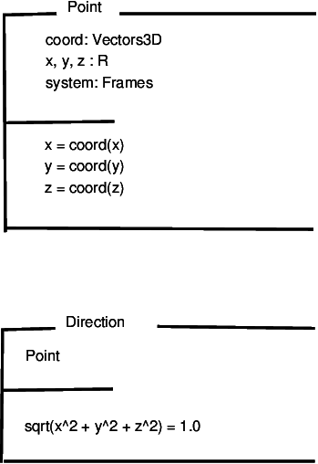
Some schemas from the RSDIMU specification:
The first schema says that a “Point” can be described as
R)named “x”, “y”, and “z”, and byIt also says that the three real numbers and the vector are closely related – essentially the real components are just a shorthand for the corresponding components of the vector.
The second schema says that a “Direction”
|
|